Blast UE4 Mesh Editor
Blast Mesh Editor is a simple tool for viewing/editing/creating Blast Assets .
Introduction
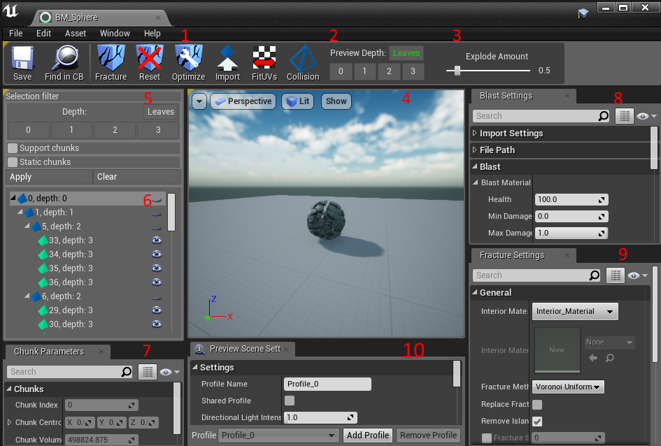
1 Toolbar - Blast mesh Processing actions.
2 Preview depth - allow to select chunks to render depending on its depth. If Leaves selected all chunks without children will be rendered.
3 Explosion Amount slider - adjust the distance between Blast Mesh origin and chunk’s render position.
4 Viewport - Blast mesh rendering.
5 Selection Filter - widget for fast chunk selection.
6 Chunk tree - shows chunk hierarchy.
7 Chunk properties
8 Blast Mesh Settings
9 Fracture Settings - General and selected fracture method settings.
10 Preview Settings - Allow to adjust viewport settings like lighting, background etc.
Importing
Importing from a Blast File
If you have a Blast Asset generated by AuthoringTool, ArtistTool or another tool, you can import it by pressing the Import button in Content Browser and selecting the appropriate *.blast file (or just dragging a *.blast file into Content Browser). You will see the import dialog. Note that *.blast files do not contain mesh geometry and you should also provide the *.fbx file which was generated with it.
Currently only importing of *.blast file with lowlevel asset in it is supported, so if you use one of the tools mentioned above (from Blast SDK) make sure it exports the lowlevel asset (usually it is –ll flag).
Authoring tool call example: AuthoringTool_x64.exe –proto –fbx –fbxcollision –ll ball.fbx ball
Apex importer call example: ApexImporter_x64.exe –fbx –fbxcollision –ll -n table -o D:Assets -f table.apb
AuthoringTool can generate assets with or without collision geometry. If your .fbx does not contain collision geometry, uncheck the *Import Collision Geometry option. The UE4 FbxImporter will generate it instead. Note: it may take a lot of time.
Import from static mesh
Creating new Blast Asset from static mesh - right click on static mesh in Content Browser and select Create Blast Mesh
Import root chunk for current asset - open Blast Mesh Editor and click on: ![]()
Viewport
Default UE4 Veiwport camera control is supported.
The user can select chunks by clicking on them (hold Ctrl for multiple selection). Bounding boxes will be drawn for selected chunks.
Rendering settings can be adjusted in the Preview Settings tab.
Blast specific viewport show options
- Fracture visualization - Show fracture method specific visualization, for example, cut plane for Cut fracture.
- Bounding box - Show axis aligned bounding box for selected chunks.
- Collision mesh - Show collision mesh wireframe rendering for visible chunks.
- Voronoi sites - Show Voronoi sites rendering for selected chunks.
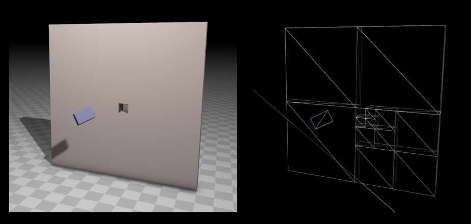
Vector picking in viewport
User may pick vector in viewport for fracture parameters of FVector type by clicking on ![]() at the right of parameter in Fracture Settings tab.
at the right of parameter in Fracture Settings tab.
Next toolbar should appear at the top right corner of viewport:
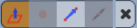
There is 4 methods for picking vector:
 Normal - Click on any chunk to pick the same normal as in clicked position
 - Point - Click on any chunk for picking position.
 - Two Points - Click twice on any chunks for picking vector between this two positions.
 - Three Points - Click twice on any chunks for picking line, then pick position on this line.
Chunk Selection
Chunks can be selected from Viewport, from Chunk Tree or by Selection filter. To clear the selection, just click in some empty space of Viewport or Chunk Tree.
Selection Filter
Select appropriate selection options and press Apply for selecting chunks. Clear will reset selection options to default.
Chunk Tree Nodes
Each node corresponds to a chunk in Blast Asset. Node name shows chunk’s ID and Depth. Root chunk’s ID will always be equal to 0. Chunk Depth is the distance in tree between the current chunk and the root chunk. Chunk’s icons exhibit some properties of chunk:
 - just a chunk
 - static chunk (chunk will be created as static body during simulation)
 - support chunk
 - support, static chunk
The static flag can be set or unset from the Chunk Tree context menu. Note: parents of static chunks also become static chunks.
Authoring
For authoring, the user should select chunk(s), setup Fracture Settings and click on: ![]()
Note: Currently, Blast Mesh does not store intermediate fracture data, only the resulting fracture. The user should always start the authoring session from the root chunk.
The user can save/load default values of Fracture Settings by clicking Save As Default and Load Default under Advanced section of General settings.
General Authoring settings
- Fracture Method
- Replace Fractured Chunk - If set, new chunks replace the fractured chunk on its depth level, otherwise they will be added as children. This flag has no effect for the root chunk, fractured chunks will be added as its children.
- Remove Islands - If set, the fracture tool will produce a new chunk for each unconnected convex, otherwise chunks which contain as few unconnected convexes as possible.
- Fracture Seed - If set, specified fracture seed will be used, otherwise fracture seed will be generated randomly. Set it for reproducing the same fracture and unset for fracture diversity.
- Default Support Depth - Fractured chunks will be support chunks if their depth is the same as Default Support Depth or, if it has no children and its depth is less than Default Support Depth.
- Interior Material - The material for internal faces of fractured chunks. External materials will be inherited from the root chunk.
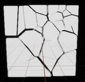
Voronoi fracture
Voronoi fracturing is based on generating Voronoi cells from cloud of internal points. Generation anisotropic and rotated cells is supported. There is many ways to generate cloud of points in Blast Mesh Editor.
General Voronoi Settings
- Force Reset - if set all previously generated Voronoi sites for selected chunks will be removed
- Cell Anisotropy - cell scale along X, Y, Z axis.
- Cell Rotation - cell rotation around X, Y, Z axis. Has no effect without cell anisotropy.
Voronoi Uniform fracture
Simple uniform Voronoi fracturing. Try this first!
Settings
- Cell Count - the number of Voronoi cell sites.
Clustered Voronoi fracture
Specified number of clusters will be generated in volume. Most of cells will be generated inside cluster (cluster is a sphere with specified radius).
Settings
- Cluster Count - the number of voronoi cluster counts.
- Cluster Radius - Voronoi cluster radius.
- Cell Count - the number of Voronoi cell sites.
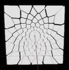
Radial fracture
Generates sites for Voronoi fracture with radial pattern.
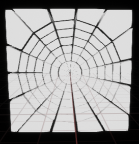
Settings
- Origin - the center of generated pattern.
- Normal - the normal to plane in which sites are generated.
- Radius - the pattern radius.
- Angular Steps - the number of angular steps.
- Radial Steps - the number of radial steps.
- Angle Offset - the angle offset at each radial step.
- Variablity - the randomness of sites distribution.
Voronoi In Sphere Fracture
Basically the same as Clustered Voronoi with Cluster Count = 1, but user can interactively pick location for the sphere center.
- Origin - the center of the sphere.
- Radius - the sphere radius.
- Cell Count - the number of Voronoi cell sites.
Voronoi Remove In Sphere
Remove Voronoi sites in sphere located in picked position with specified probability.
- Origin - the center of the sphere.
- Radius - the sphere radius.
- Probability * - the probability of removing cell site in sphere (0 - 1).
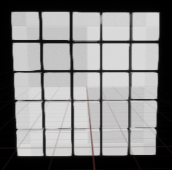
Uniform slicing fracture
Cut chunk with grid like pattern.
Settings
- Slices Count - the number of slices along X, Y, Z axis.
- Angle variation - the angle of slice will vary in range depending on this. Note: the order of chunk cutting X, Y, Z. Resulting chunks depend on order.
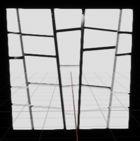
- Offset variation - the slices offset will vary in range depending on this. Note: the order of chunk cutting X, Y, Z. Resulting chunks depend on order
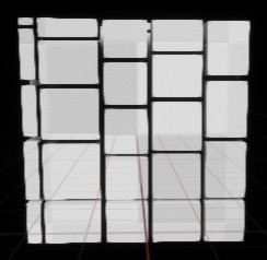
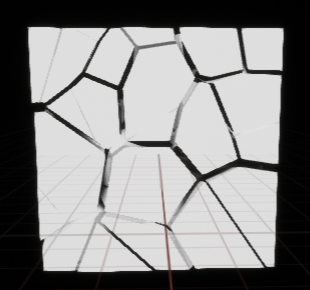
Noise
By enabling noise faces between chunks become non planar (noised).
- Noise Amplitude - amplitude of cutting surface noise. If set to 0 - noise is disabled. Reasonable values 0.005 - 0.5
- Noise Frequency - frequency of cutting surface noise. Reasonable values 0.05 - N. Where N should be less then Surface Resolution / Noise Octave Number. Note: for values below 1 skewed faces will be produced.
- Noise Octave Number - Number of octave of cutting surface noise. Reasonable maximal value limited by Surface Resolution.
- Surface Resolution - Number of cutting surfaces applied to fractured chunks. For large values (> 50) may lead to significant slowdown of fracturing.
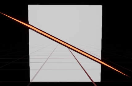
Cut Fracture
It allows to split chunk(s) with specified plane. Noise can be applied to this plane, see Noise.
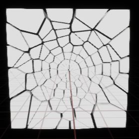
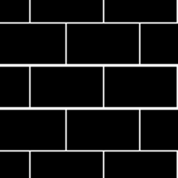
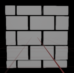
Cutout fracture
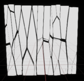
Cut chunk with user specified pattern. Pattern is a texture where black regions assumed as chunks projections and white lines are boundaries between projections.
Note: this boundaries should be closed to each other or to texture boundaries.
Settings
- Pattern - user specified texture for cutout.
- Origin - the center of pattern.
- Normal - the normal to the plane to which applied the Pattern.
- Size - the size of the pattern in length unit.
- Rotation Z - the rotation of pattern around Normal and Origin in degree.
- Periodic - Use periodic boundary condition when applying Pattern. Not yet implemented!
- Fill Gaps - Fill gaps in Pattern. Each partition will be expanded until the boundaries of other partitions.
Noise can be applied to this fracture, see Noise.
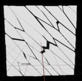
Below pattern of brick wall and resulting fracture:
Reset Fracture
If you want to remove all children for selected chunk(s). Just pick it in Chunk tree and click on ![]() or right click on chunk in tree and select Remove children in context menu. To remove fracture completely select root chunk.
or right click on chunk in tree and select Remove children in context menu. To remove fracture completely select root chunk.
Optimize Fracture
For better chunk hierarchy (see Authoring Recommendations)user might try to optimize fracture by clicking on ![]()
Settings
- Threshold - If number of children of some chunk less then Threshold then it would be considered as already optimized and skipped.
- Targeted cluster size - Maximum number of children for processed chunks.
Fit UV coordinates to given size
By default UV coordinates stretched from 0 to 1 for mesh cube bounding box. All children UVs mapped from corresponding UVs of this box.
User may adjust the UV coordinates scale by clicking on ![]() .
.
Settings
- Square size - the size of UV coordinates applied to the chunks.
- Fit UV for only selected chunks - If it is not chosen then UV will be scaled for all chunks.
Rebuld collision mesh
By default collision mesh for each chunks is just a single convex hull. It might be a problem for complex geometry. So user can perform convex decomposition by clicking on ![]() for all or for selected chunks.
for all or for selected chunks.
Settings
- Is Only for Selected Chunks - If it is not chosen then collision mesh will be rebuilt for all chunks.
- Maximum Number Of Hulls - Maximum number of convex hull generated for one chunk. If equal to 1 convex decomposition is disabled.
- Voxel Grid Resolution - Voxel grid resolution used for chunk convex decomposition. Note convex decomposition might be very expensive when this parameter exceed default value.
- Concavity - Controls how accurate hull generation is.
Authoring Recommendations
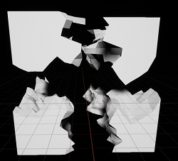
- Make deeper chunk hierarchy instead of flat. At any given moment Blast shows the biggest chunks possible to reduce graphics and physics load. So for example if you want to break an asset into 100 pieces, instead of having root chunk split in 100 subchunks you can split root in 4 big pieces, then each into 5 more, and then each of those into 5 more, in total 4 * 5 * 5 = same 100 pieces on the leaves of tree. But if say only one piece was detached it would not draw all 99 others, only about 10 would be required to be shown. Example of showing the biggest chunks possible:
Also there is an option for uniting chunks and building chunk hierarchy. Just click on ![]()
- By default, Support Graph is set on the deepest level of hierarchy (leaf chunks), which is generally good. But if your leaf chunks are really small, dust-like, there is no need to keep Support Graph on that level. Blast has subsupport fracture, where chunks lower than support level have their own health and just split into all subchunks when damaged enough. You can explicitly set Support Depth to tweak Support Graph resolution. View Support Graph with debug render setting.